- blog
3D depth sensing for robots 101
It is no secret that we are all about Autonomous Mobile Robots at Gideon. There’s a lot of driving and carrying stuff around that happens in our warehouses daily. But, all of it would not be possible without a key piece of technology – the ability to perceive and measure three-dimensional space.
The sensor technologies behind autonomous navigation
This remarkable ability is a vital prerequisite for true autonomy in unstructured, chaotic environments. So let’s do it justice and take an in-depth look into the sensor technologies which deliver the 3D information required for autonomous navigation.
LiDAR
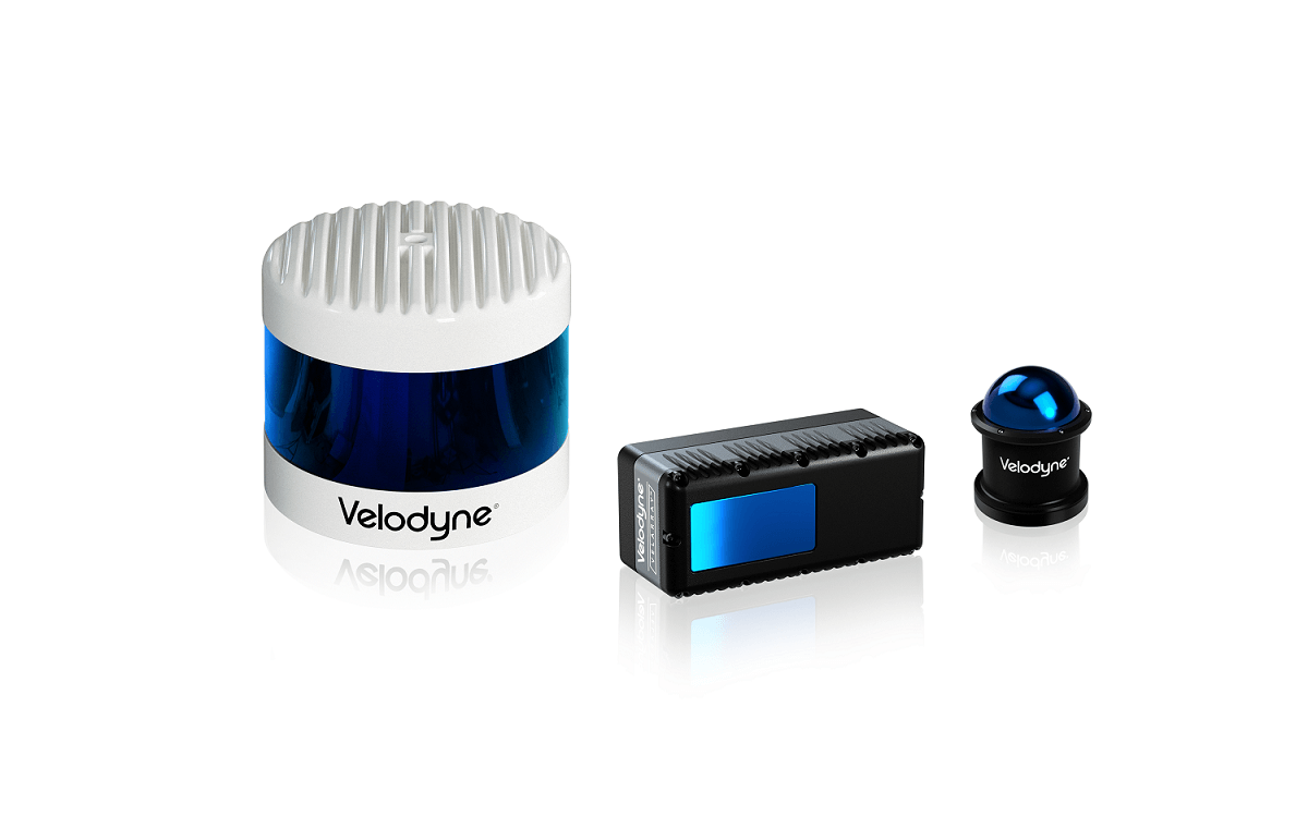
Example of various LIDARs useful for autonomous navigation and driving. Source
One of the most common sensors in autonomous driving applications is the LiDAR, or laser rangefinder sensor. LiDAR works by sending out pulses of (usually infrared) light in a tight beam to a distant object, then measuring the time it takes for the reflected light to return.
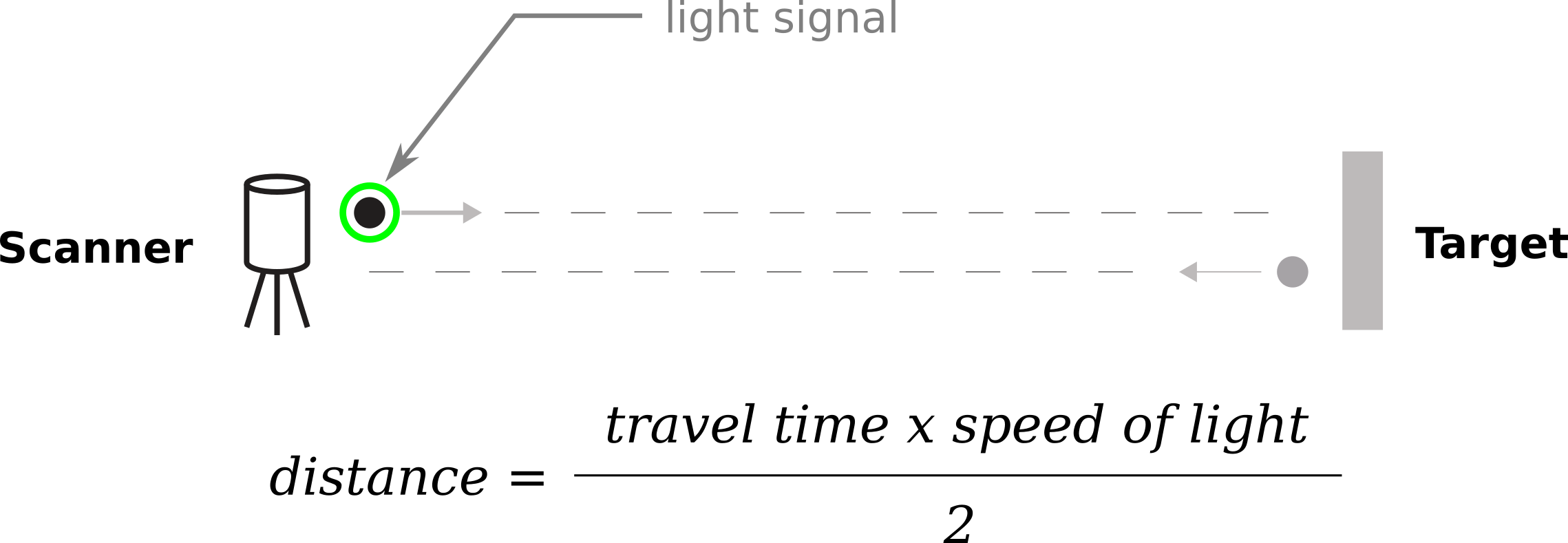
Basic operating principle of LIDAR. Source
By multiplying the measured time with the speed of light, distance is obtained.
The beam is scanned with various mechanical and optical methods in a pattern covering the three-dimensional space around the sensor – yielding a collection of measurements for the objects of the 3D space we call the point cloud.
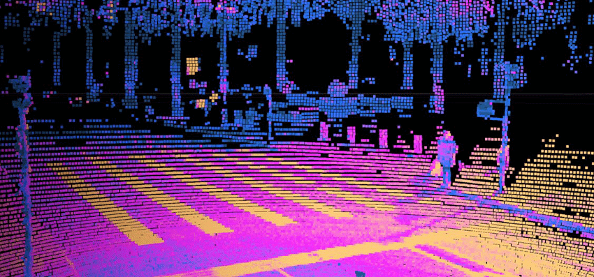
An example of a point cloud from a LIDAR. Source
LIDARs can have a 360° field of view; they are accurate to a centimeter even at longer distances and work with low latencies. They are not affected by ambient light or temperature. All this makes them very suitable for autonomous cars, which move at higher speeds.
However, LIDARs are not without limitations: the point cloud is sparse as the performance of the scanning mechanism limits the spatial resolution.
Adverse weather such as rain and fog and the surface’s reflectivity can suppress the intensity of the returning light, leading to an incorrect measurement.
On top of everything, LIDARs are complex devices with rotating parts, usually expensive and susceptible to mechanical damage.
In general, LIDARs are very applicable for high-speed/long-range measurement applications and work great for autonomous mobile robots – where they are indispensable for safety. However, especially in unstructured environments, they may provide less context information than required, so they usually complement other sensors, such as cameras.
Time-of-Flight cameras
Based on a similar principle, the Time-of-Flight (ToF) camera attempts to measure the time required for a light pulse to reach a target and return to the origin (the sensor). However, the ToF camera does not send out directed beams of light.
Instead, an illumination unit sends light pulses from the camera, illuminating the entire scene imaged in synchronicity with the emitted light.
The camera takes two pictures, the first one while the illumination is on and the second one when it’s off. The ToF camera then compares the intensity information and derives the flight time and the range.
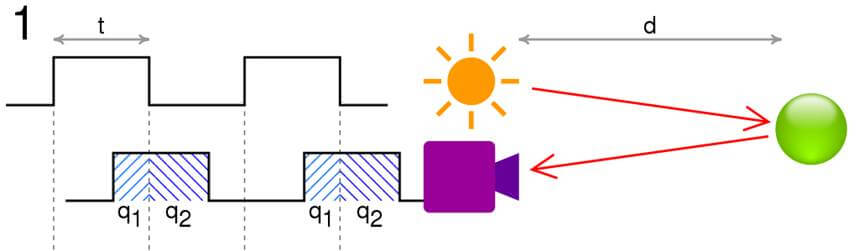
The distance, d = c t/2 q2/q1 + q2 , where c is the speed of light, t is the length of the pulse, q1 is the accumulated charge in the pixel when light is emitted and q2 is the accumulated charge when it is not. Source
Therefore, time of flight cameras are like a “scanner-less” LiDAR, providing centimeter- or sub-centimeter-accurate distances in a dense depth map with a corresponding point cloud.>
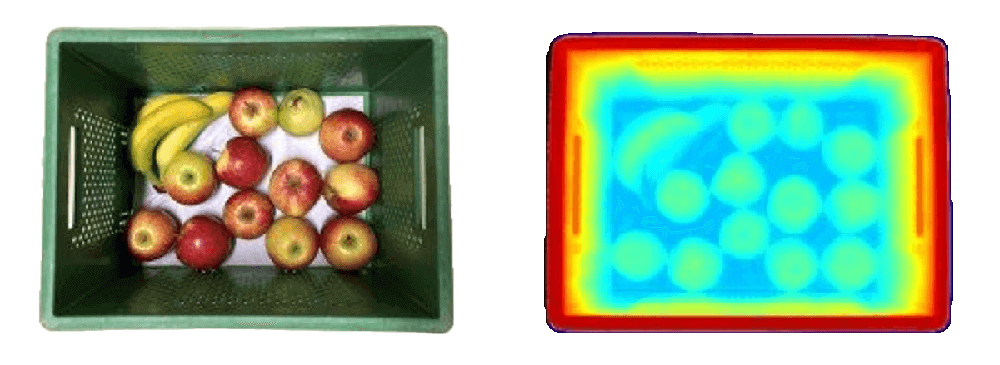
ToF depth map. Source
However, unlike LiDAR, their field of view is limited to the camera lens view. As the light of the illuminator spreads out rather than collimates in a beam, its illumination power will drop off significantly after only a few meters.
Most ToF cameras have a limited range of around 6 to 9 meters – this is more than enough for many applications requiring precise distances, such as object manipulation.
Structured light sensors
A structured light sensor also works by emitting light. But, instead of measuring the time it takes for the light to travel the distance, it uses patterns of (usually visible) light to encode information into the points of an illuminated object.
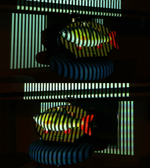 Example of structured light patterns.
 Example of structured light patterns. Source
By observing the light pattern distorted by the scene, the depth information can be derived for each illuminated pixel of the camera image.
Structured light sensors can be sub-millimeter-precise, but their application is limited because the most precise results usually require illuminating the scene with multiple patterns, which hinders application on mobile platforms.
Using visible light projectors comes with a couple of challenges; it is not suited for outdoor/daylight conditions, and safety requirements need to be met to protect the eyes of personnel.
Structured light 3D sensors are mainly used indoors on assembly lines or bin-picking operations, not on autonomous platforms.
All of the previously mentioned and explained sensors are considered active sensors – they actively emit light to obtain measurements.
While this gives them an edge in adverse conditions such as low light, eye safety and outdoor/daylight operation can present serious challenges for these sensors – challenges that can be addressed with a passive stereo vision sensor.
Stereo vision sensors
One might associate the word “stereo” solely with having two distinct viewpoints. And yes, most stereo vision sensors have at least two cameras. However, the word “stereo” comes from the Greek word stereos – meaning “solid.” Therefore, stereo vision is the perception of solid objects in 3D space and can be achieved to an extent even with a single camera (or more than two cameras).
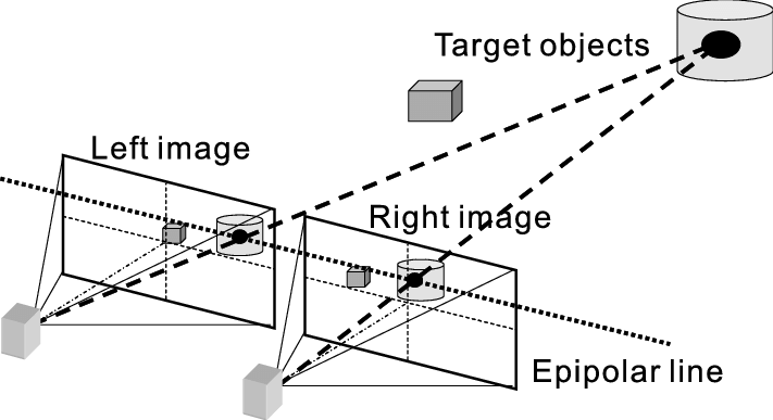
Stereo imaging and epipolar geometry. Hariyama, Masanori & Yokoyama, Naoto & Kameyama, Michitaka. (2008). Design of a Trinocular-Stereo-Vision VLSI Processor Based on Optimal Scheduling. IEICE Transactions on Electronics. 91-C. 479-486. 10.1093/ietele/e91-c.4.479.
However, the most common one is the binocular stereo vision sensor. It images the scene with two camera viewpoints separated by a distance, usually called the baseline.
By calibrating the cameras and utilizing the concept of epipolar geometry, it rectifies the two camera images. It then compares them with the stereo vision algorithm line by line, searching for pixel correspondences in a process called stereo matching.
The distance between individual corresponding pixels is called disparity – the final information needed to triangulate the depth. The other two are the previously mentioned focal length and the baseline.
Stereo matching is an extremely prolific research area, and searching for correspondence can be performed in many ways, utilizing methods from simple block matching with cost functions such as the census transform to complex convolutional neural networks.
However, most stereo vision sensors use the semi-global matching algorithm today, which offers real-time performance and yields solid quality results.
The benefits of stereo vision sensors in robotics
Stereo vision sensors are more robust in conditions where active sensors may fail – they do not depend on light emission and have no problem operating in broad daylight.
Modern digital cameras can provide high-quality images, which allow algorithms to estimate detailed, dense disparity/depth maps. Additionally, they can easily adapt to indoor and outdoor activity and are far less expensive than active sensors.
An important advantage of the stereo vision sensor is the native ability to extract a high-quality color image well-aligned to the depth map. The color image can be processed by a neural network or another method for detecting objects and providing semantic information through semantic image segmentation.
For example, the color and semantic information can be fused with depth to assist the robot in navigation, highlighting dynamic obstacles or removing them from the mapping process.
Stereo vision sensors are thus an excellent choice for robot navigation and mapping in diverse, unstructured environments.
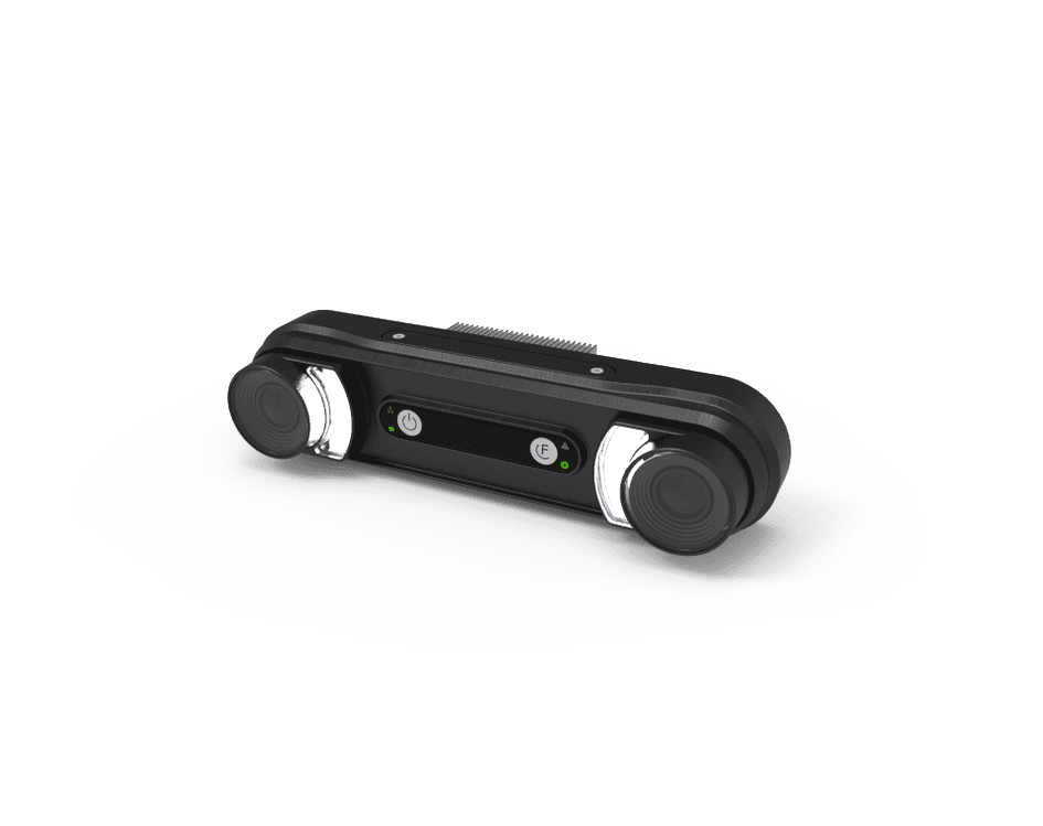
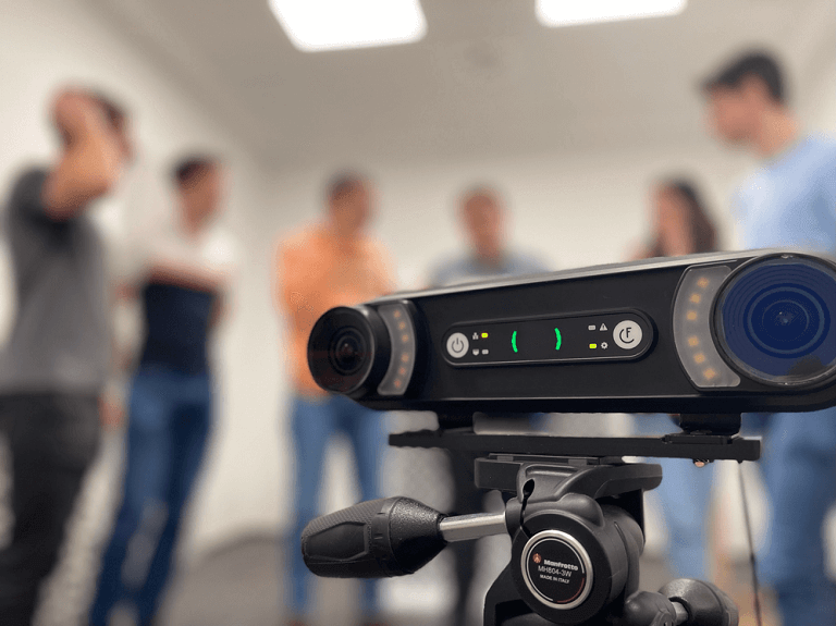
Gideon Vision module – example of a stereo vision camera.
Stereo vision sensors deficiencies and how we at Gideon mitigate them
Stereovision sensors are not perfect. One of their drawbacks stems from the inverse relation of depth and disparity. For lower disparities (which correspond to larger depths), a small error in disparity estimation yields a large error in depth.
Therefore, stereo vision sensors are most accurate at close range, with the definition of “close range” mainly depending on the baseline. While cameras with larger baselines are more accurate, increasing the baseline also affects other camera parameters, such as the minimum measurable depth.
Additionally, stereo vision sensors are sensitive to specific surfaces and conditions in the scene, as they require texture or information in an image area to find a match. In low-textured or reflective areas, matching with commonly used methods such as the census transform often fails, yielding spurious results.
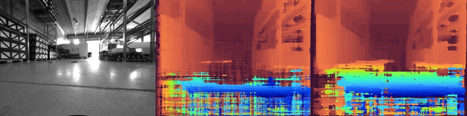
Left: left camera image frame. Middle: stereo depth obtained using the Census transform and Semi-Global matching. Right: stereo depth for the same frame obtained with Gideon’s in-house algorithm. Notice the improvement in the reflective floor surface.
Advanced AI-powered algorithms, such as the ones implemented in Gideon’s Vision Module, can outperform traditional, commonly used methods by enhancing the ability of the algorithm to work on challenging and ambiguous surfaces.
The final word on 3D depth sensing technologies
With this, we conclude the overview of 3D depth sensing technologies that provide mobile robots with situational awareness and enable them to work on complex tasks alongside people. While many other methods exist, you probably won’t find them on a robot near you.
For most autonomous robotic systems, a combination of the sensors above will yield a robotic system able to move and perform tasks autonomously, relying on multiple sensors, depending on the situation around it.
If you want to learn more about how we solved the perception and measurement of three-dimensional space – so our robots can drive around – visit our technology page and see for yourself.